Translate

Search This Blog

Total Pageviews

Friday, January 26, 2024

Number(Numeral) Systems

 2.1 INTRODUCTION 

A number system (or numeral system) defines how a number can be represented using distinct symbols. A number can be represented differently in different systems. For example, the two numbers (2A)16 and (52)8 both refer to the same quantity, (42)10, but their representations are different.

As we use symbols (characters) to represent words in a natural language, we use symbols (digits) to represent numbers. However, we know that the number of symbols (characters) in any language is limited. We need to repeat characters and combine them to create words. It is the same for numbers: we have a limited number of symbols (digits) to represent numbers, which means that the digits need to be repeated and combined. 

Several number systems have been used in the past and can be categorized into two groups: positional systems and non-positional systems. Our main goal is to discuss the positional number systems, but we also give examples of non-positional systems.


2.2 POSITIONAL NUMBER SYSTEMS 

In a positional number system, the position a symbol occupies in the number determines the value it represents. In this system, a number represented as: 

 has the value of: 
in which S is the set of symbols, b is the base (or radix), which is equal to the total number of the symbols in the set S, and SK and SL are symbols in the whole and fraction parts of the number. 

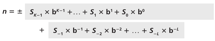
Note that we have used an expression that can be extended from the right or from the left. In other words, the power of b can be 0 to K - 1 in one direction and -1 to -L in the other direction. The terms with non negative powers of b are related to the integral part of the number, while the terms with negative power of b are related to the fractional part of the number. The +- sign shows that the number can be either positive or negative.

2.2.1 The decimal system (base 10) 

The first positional number system we discuss is the decimal system. The word decimal is derived from the Latin root decem (ten). In this system the base b = 10 and we use ten symbols to represent a number. The set of symbols is S = {0, 1, 2, 3, 4, 5, 6, 7, 8, 9}. As we know, the symbols in this system are often referred to as decimal digits or just digits. We use +- to show that a number can be positive or negative, but remember that these signs are not stored in computers—computers handle the sign differently.

In the decimal system for simplicity, we often drop the parentheses, the base, and the plus sign if the number is positive. For example, we write the number (552.23)10 as 552.23—the base and plus signs are implicit.

 Integers 

An integer (an integral number with no fractional part) in the decimal system is familiar to all of us—we use integers in our daily life. In fact, we have used them so much that they are intuitive. We represent an integer as +- SK–1 … S1 S0. The value is calculated as:

in which Si is a digit, b = 10 is the base, and K is the number of digits. 

Another way to show an integer in a number system is to use place values, which are powers of 10 (100, 101, …, 10K-1) for decimal numbers. Figure 2.1 shows an integer in the decimal system using place values. 


Example 2.1 

The following shows the place values for the integer +224 in the decimal system:

Note that the digit in position 1 has the value 20, but the same digit in position 2 has the value 200. Also note that we normally drop the plus sign, but it is implicit.

Example 2.2 

The following shows the place values for the decimal number –7508. We have used 1, 10, 100, and 1000 instead of powers of 10:


Maximum value 

Sometimes we need to know the maximum value of a decimal integer that can be represented by K digits. The answer is Nmax = 10K - 1.  For example, if K = 5, then the maximum value is Nmax = 105 - 1 = 99 999.


Reals 

A real (a number with a fractional part) in the decimal system is also familiar. For example, we use this system to show dollars and cents ($23.40). We can represent a real as +- SK–1 … S1 S0 . S–1 … S–L. The value is calculated as:

in which S1 is a digit, b = 10 is the base, K is the number of digits in the integral part, and L is the number of digits in the fractional part. The decimal point we use in our representation separates the fractional part from the integral part.

Example 2.3 

The following shows the place values for the real number +24.13:


2.2.2 The binary system (base 2) 

The second positional number system we discuss is the binary system. The word binary is derived from the Latin root bini (or two by two). In this system the base b = 2 and we use only two symbols, S = {0, 1}. The symbols in this system are often referred to as binary digits or bits (binary digit). As we will see, data and programs are stored in the computer using binary patterns, a string of bits. This is because the computer is made of electronic switches that can have only two states, on and off. The bit 1 represents one of these two states and the bit 0 the other.


Integers 

We can represent an integer as +- (SK–1 … S1 S0)2. The value is calculated as:

in which Si is a digit, b = 2 is the base, and K is the number of bits. Another way to show a binary number is to use place values (20, 21, … 2K-1). Figure 2.2 shows a number in the binary number system using place values:

Example 2.4 

The following shows that the number (11001)2 in binary is the same as 25 in decimal. The subscript 2 shows that the base is 2:

Note that the equivalent decimal number is N = 16 + 8 + 0 + 0  1 = 25.

Maximum value 

The maximum value of a binary integer with K digits is Nmax = 2K – 1. For example, if K = 5, then the maximum value is Nmax = 25 – 1 = 31.


Reals 

A real—a number with an optional fractional part—in the binary system can be made of K bits on the left and L bits on the right, +- (SK–1 … S1 S0 . S–1 … S–L)2. The value can be calculated as:

in which Si is a bit, b = 2 is the base, K is the number of bits to the left, and L is the number of bits to the right of the decimal point. Note that K starts from 0, but L starts from -1. The highest power is K - 1 and the lowest power is -L.

Example 2.5

The following shows that the number (101.11)2 in binary is equal to the number 5.75 in decimal:

Note that the value in the decimal system is R = 4 + 0 + 1 + 0.5 + 0.25 = 5.75.


2.2.3 The hexadecimal system (base 16) 

Although the binary system is used to store data in computers, it is not convenient for representation of numbers outside the computer, as a number in binary notation is much longer than the corresponding number in decimal notation. However, the decimal system does not show what is stored in the computer as binary directlythere is no obvious relationship between the number of bits in binary and the number of decimal digits. Conversion from one to the other is not fast, as we will see shortly. 

To overcome this problem, two positional systems were devised: hexadecimal and octal. We first discuss the hexadecimal system, which is more common. The word hexadecimal is derived from the Greek root hex (six) and the Latin root decem (ten). To be consistent with decimal and binary, it should really have been called sexadecimal, from the Latin roots sex and decem. In this system the base b = 16 and we use 16 symbols to represent a number. The set of symbols is S = {0, 1, 2, 3, 4, 5, 6, 7, 8, 9, A, B, C, D, E, F}. Note that the symbols A, B, C, D, E, F (uppercase or lowercase) are equivalent to 10, 11, 12, 13, 14, and 15 respectively. The symbols in this system are often referred to as hexadecimal digits.


Integers 

We can represent an integer as +- SK–1 … S1 S0. The value is calculated as:

in which Si is a digit, b = 16 is the base, and K is the number of digits. Another way to show a hexadecimal number is to use place values (160, 161, …, 16K-1). Figure 2.3 shows a number in the hexadecimal number system using place values.
 

Example 2.6 

The following shows that the number (2AE)16 in hexadecimal is equivalent to 686 in decimal:

Note that the value in the decimal system is N = 512 + 160 + 14 = 686. 

 Maximum value 

The maximum value of a hexadecimal integer with K digits is Nmax = 16K – 1. For example, if K = 5, then the maximum value is Nmax = 165 – 1 = 1 048 575.


Reals 

Although a real number can be also represented in the hexadecimal system, it is not very common.


2.2.4 The octal system (base 8)

The second system that was devised to show the equivalent of the binary system outside the computer is the octal system. The word octal is derived from the Latin root octo (eight). In this system the base b = 8 and we use eight symbols to represent a number. The set of symbols is S = {0, 1, 2, 3, 4, 5, 6, 7}. The symbols in this system are often referred to as octal digits. Integers We can represent an integer as +- SK–1 … S1 S0. The value is calculated as:

in which Si is a digit, b = 8 is the base, and K is the number of digits. Another way to show an octal number is to use place values (80, 81, …, 8K-1).­ Figure 2.4 shows a number in the octal number system using place values.

Example 2.7

 The following shows that the number (1256)8 in octal is the same as 686 in decimal:

Note that the decimal number is N = 512 + 128 + 40 + 6 = 686. 

Maximum Value 

The maximum value of an octal integer with K digits is Nmax = 8K − 1. For example, if K = 5, then the maximum value is Nmax = 85 − 1 = 32767. 


Reals 

Although a real number can be also represented in the octal system, it is not very common.


2.2.5 Summary of the four positional systems 

Table 2.1 shows a summary of the four positional number systems discussed .

Table 2.2 shows how the number 15 is represented with 

two digits in decimal, 

four digits in binary, 

two digits in octal, and 

only one digit in hexadecimal. 

The hexadecimal representation is definitely the shortest.


2.2.6 Conversion 

We need to know how to convert a number in one system to the equivalent number in another system. Since the decimal system is more familiar than the other systems, we first show how to covert from any base to decimal. Then we show how to convert from decimal to any base. Finally, we show how we can easily convert from binary to hexadecimal or octal and vice versa. 


Any base to decimal conversion 

This type of conversion is easy and fast. We multiply each digit with its place value in the source system and add the results to get the number in the decimal system. Figure 2.5 shows the idea.


Example 2.8 

The following shows how to convert the binary number (110.11)2 to decimal: (110.11)2 = 6.75:

Decimal: 6.75


Example 2.9 

The following shows how to convert the hexadecimal number (1A.23)16 to decimal:

Decimal: 26.137 

Note that the result in the decimal notation is not exact, because 3 x 16-2 = 0.01171875. We have rounded this value to three digits (0.012). In other words, (1A.23)16 ≈ 26.137. When we convert a number in decimal to hexadecimal, we need to specify how many digits we allow to the right of the decimal point.


Example 2.10 

The following shows how to convert (23.17)8 to decimal:

This means that (23.17)8 ≈ 19.234 in decimal. Again, we have rounded up 7 x 8-2 = 0.109375. 


Decimal to any base conversion

We can convert a decimal number to its equivalent in any base. We need two procedures, one for the integral part and one for the fractional part.

We call the integral part of the decimal number the source and the integral part of the converted number the destination. We first create an empty destination. We then repetitively divide the source to get the quotient and the remainder. The remainder is inserted to the left of the destination. The quotient becomes a new source. Figure 2.7 shows how the destination is made with each repetition.

We use Figure 2.6 to illustrate the process manually with some examples. 

Example 2.11 

The following shows how to convert 35 in decimal to binary. We start with the number in decimal, we move to the left while continuously finding the quotients and the remainder of division by 2. The result is 35 = (100011)2:

Example 2.12 

The following shows how to convert 126 in decimal to its equivalent in the octal system. We move to the right while continuously finding the quotients and the remainder of division by 8. The result is 126 = (176)8:


Example 2.13 

The following shows how we convert 126 in decimal to its equivalent in the hexadecimal system. We move to the right while continuously finding the quotients and the remainder of division by 16. The result is 126 = (7E)16:


Converting the fractional part 

The fractional part can be converted using repetitive multiplication. We call the fractional part of the decimal number the source and the fractional part of the converted number the destination. We first create an empty destination. We then repetitively multiply the source to get the result. The integral part of the result is inserted to the right of the destination, while the fractional part becomes the new source. Figure 2.8 shows the UML diagram for the process. Figure 2.9 shows how the destination is made in each repetition. We use the figure to illustrate the process manually with some examples.


Example 2.14 

Convert the decimal number 0.625 to binary. 

Solution 

Since the number 0.625 has no integral part, the example shows how the fractional part is calculated. The base here is 2. Write the decimal number at the left corner. Multiply the number continuously by 2 and record the integral and fractional part of the result. The fractional part moves to the right, and the integral part is recorded under each operation. Stop when the fractional part is 0 or there are enough bits. The result is (0.101)2:


Example 2.15 

The following shows how to convert 0.634 to octal using a maximum of four digits. The result is 0.634 = (0.5044)8. Note that we multiply by 8 (base octal):


Example 2.16 

The following shows how to convert 178.6 in decimal to hexadecimal using only one digit to the right of the decimal point. The result is 178.6 = (B2.9)16 Note that we divide or multiply by 16 (base hexadecimal):


Example 2.17 

An alternative method for converting a small decimal integer (usually less than 256) to binary is to break the number as the sum of numbers that are equivalent to the binary place values:

 Using this table, we can convert 165 to binary (10100101)2 as shown below:


Example 2.18 

A similar method can be used to convert a decimal fraction to binary when the denominator is a power of two:

Using this table, we convert 27⁄64 to binary (0.011011)2 as shown below:

Align these fractions according to decimal equivalent values. Note that since 1⁄2 and 1⁄16 are missing, we replace them with 0s:


Number of digits 

We often need to know the number of digits before converting a number from decimal to other bases. In a positional number system with base b, we can always find the number of digits of an integer using the relation K = ⎡logb N⎤, in which ⎡x⎤ means the smallest integer greater than or equal to x (it is also called the ceiling of x), and N is the decimal value of the integer. For example, we can find the required number of bits in the decimal number 234 in all four systems as follows: 

a.  In decimal: Kd = ⎡log10 234⎤ = ⎡2.37⎤ = 3, which is obvious. 

b.  In binary: Kb = ⎡log2 234⎤ = ⎡7.8⎤ = 8. This is true because 234 = (11101010)2 

c.  In octal: Ko = ⎡log8 234⎤ = ⎡2.62⎤ = 3. This is true because 234 = (352)8 

d. In hexadecimal: Kh = ⎡log16 234⎤ = ⎡1.96⎤ = 2. This is true because 234 = (EA)16


Binary–hexadecimal conversion 

We can easily change a number from binary to hexadecimal and vice versa. The reason is that there is a relationship between the two bases: four bits in binary is one digit in hexadecimal. Figure 2.10 shows how this conversion can be done.


Example 2.19 

Show the hexadecimal equivalent of the binary number (10011100010)2

We first arrange the binary number in 4-bit patterns start from far right: 100 1110 0010. Note that the leftmost pattern can have one to four bits. We then use the equivalent of each pattern shown in Table 2.2 in section 2.2.5 to change the number to hexadecimal: (4E2)16.


Example 2.20 

What is the binary equivalent of (24C)16

Each hexadecimal digit is converted to 4-bit patterns: 2 → 0010, 4 → 0100, and C → 1100. The result is (001001001100)2.


Binary–octal conversion 

We can easily convert a number from binary to octal and vice versa. The reason is that there is an interesting relationship between the two bases: three bits is one octal digit. Figure 2.11 shows how this conversion can be done.


Example 2.21 

Show the octal equivalent of the binary number (101110010)2

Each group of three bits is translated into one octal digit. The equivalent of each 3‑bit group is shown in Table 2.2 in section 2.2.5. The result is (562)8.


Example 2.22

 What is the binary equivalent of for (24)8

Write each octal digit as its equivalent bit pattern to get (010100)2.


Octal–hexadecimal conversion 

It is not difficult to convert a number in octal to hexadecimal or vice versa. We can use the binary system as the intermediate system. Figure 2.12 shows an example.

The following illustrates the process: 

❑ To convert from octal to hexadecimal, we first convert the number in the octal system to binary. We then rearrange the bits in groups of four bits to find the hexadecimal equivalent. 

❑ To convert from hexadecimal to octal, we first convert the number in the hexadecimal system to binary. We then rearrange the bits in groups of three to find the octal ­equivalent. 


Number of digits 

In conversion from one base to another, we often need to know the minimum number of digits we need in the destination system if we know the maximum number of digits in the source system. For example, if we know that we use at most six decimal digits in the source system, we want to know the minimum number of binary digits we need in the destination system.

 In general, assume that we are using K digits in base b1 system. The maximum number we can represent in the source system is b1K – 1. The maximum number we can have in the destination system is b2x – 1. Therefore, b2x – 1 ≥ b1K – 1. This means b2x ≥ b1K, which means:


Example 2.23 

Find the minimum number of binary digits required to store decimal integers with a maximum of six digits. 

K = 6, b1 = 10, and b2 = 2. Then x = ⎡K x (log b1 / log b2)⎤ = ⎡6 x (1 / 0.30103)⎤ 5 20. The largest six-digit decimal number is 999 999 and the largest 20-bit binary number is 1 048 575. Note that the largest number that can be represented by a 19-bit number is 524287, which is smaller than 999 999. We definitely need 20 bits.


 2.3 NONPOSITIONAL NUMBER SYSTEMS 

Although non-positional number systems are not used in computers, we give a short review here for comparison with positional number systems. A non-positional number system still uses a limited number of symbols in which each symbol has a value. However, the position a symbol occupies in the number normally bears no relation to its value—the value of each symbol is fixed. To find the value of a number, we add the value of all symbols present in the representation. In this system, a number is represented as:

 and has the value of:

There are some exceptions to the addition rule we just mentioned, as shown in Example 2.24. 


Example 2.24

 The Roman number system is a good example of a non-positional number system. This system was invented by the Romans and was used until the sixteenth century in Europe. Roman numerals are still used in sports events, clock dials, and other applications. This number system has a set of symbols S = {I, V, X, L, C, D, M}. The values of each symbol are shown in Table 2.3.

To find the value of a number, we need to add the value of symbols subject to specific rules: 

  1. When a symbol with a smaller value is placed after a symbol having an equal or larger value, the values are added.
  2. When a symbol with a smaller value is placed before a symbol having a larger value, the smaller value is subtracted from the larger one. 
  3. A symbol S1 cannot come before another symbol S2 if S1 ≤ 10 x S2. For example, I or V cannot come before C. 
  4. For large numbers a bar is placed above any of the six symbols (all symbols except I) to express multiplication by 1000. For example, V = 5 000 and M = 1 000 000. 
  5. Although Romans used the word nulla (nothing) to convey the concept of zero, the Roman numerals lack a zero digit in their system. 

The following shows some Roman numbers and their values:


Wednesday, January 2, 2019

Signal Paths from Analog to Digital (DACs)

The concept of a programmable system-on-chip (SoC) started in 1972 with the advent of the unassuming 4-bit TMS1000 microcomputer —the perfect fit for applications such as calculators and microwave ovens that required a device with everything needed to embed "electronic intelligence".

Microcomputers changed the way engineers approached equipment design;
  1. for the first time they could reuse proven electronics hardware, needing only to create software specific to the application. 
  2. The result of microcomputer-based designs has been a reduction in both system cost and time-to-market.
In 2005 many things have changed, but many things remain the same. The term microcomputer has been replaced with microcontroller unit (MCU) —a name more descriptive of a typical application.
Today’s MCU, just like yesterday’s microcomputer, remains the heart and soul of many systems.
  1. But over time the MCU has placed more emphasis on providing a higher level of integration and control processing and less on sheer computing power. 
  2. The race for embedded computing power has been won by the dedicated digital signal processor (DSP), a widely used invention of the ‘80s that now dominates high-volume, computing-intensive embedded applications such as the cellular telephone. But the design engineer’s most used tool, when it comes to implementing cost effective system integration, remains the MCU. The MCU allows just the right amount of intelligent control for a wide variety of applications.
  3. Today there are hundreds of MCUs readily available, from low-end 4-bit devices like those found in a simple wristwatch, to high-end 64-bit devices. But the workhorses of the industry are still the versatile 8/16-bit architectures. Choices are available with 8 to 100+ pins and program memory ranging from 1 kb to 64 KB. 
  4. The MCU’s adoption of mixed-signal peripherals is an area that has greatly expanded, recently enabling many new SoC solutions. It is common today to find MCUs with 12-bit analog-to-digital and digital-to-analog converters combined with amplifiers and power management, all on the same chip in the same device. This class of device offers a complete signal-chain on a chip for applications ranging from energy meters to personal medical devices.
  5. Modern MCUs combine mixed-signal integration with instantly programmable Flash memory and embedded emulation
  6. In the hands of a savvy engineer, a unique MCU solution can be developed in just days or weeks compared to what used to take months or years. 
  7. You can find MCUs everywhere you look from the watch on your wrist to the cooking appliances in your home to the car you drive. An estimated 20 million MCUs ship every day(2005), with growth forecast for at least a decade to come. The march of increasing silicon integration will continue offering an even greater variety of available solutions—but it is the engineer’s creativity that will continue to set apart particular system solutions.
Analog system designers many times in the past avoided the use of electronics for their system functions because electronic circuits could not provide the dynamic range of the signal
  • without severe nonlinearity, or 
  • because the circuits drifted or became unstable with temperature, or 
  • because the computations using analog signals were quite inaccurate.
As a result, the design shifted to other disciplines, for example, mechanical.

Today, young engineers requested by their superiors to design an analog control system, have an entirely new technique available to them to help them design the system and overcome the “old” problems.
The design technique is this:
  1. sense the analog signals and convert them to electrical signals;
  2. condition the signals so they are in a range of inputs to assure accurate processing; 
  3. convert the analog signals to digital; make the necessary computations using the very high-speed IC digital processors available with their high accuracy;
  4. convert the digital signals back to analog signals; and 
  5. output the analog signals to perform the task at hand.
Here we try to explain the functions that are in the signal chain, and explain how to design electronic circuits to perform the functions. What we have to know are:
  1. different types of sensors and their outputs. 
  2. different techniques of conditioning the sensor signals, especially amplifiers and op amps
  3. techniques and circuits for analog-to-digital and digital-to-analog conversions, and what a digital processor is and how it works. 
  4. data transmissions and power control
  5. assembly-language programming, and also 
  6. hands on experience on building a working project. 
  7. ability on choosing a digital processor. We choose to use TI MSP430 microcontroller because of its design, and because it is readily available, it is well supported with design and applications documentation, and it has relatively inexpensive evaluation tools.
The goal here is to provide understanding and learning of the new design technique available to analog system designers and the tools available to provide system solutions.

                                          Intro

Designers of analog electronic control systems have continually faced the following obstacles in arriving at a satisfactory design:
  1. Instability and drift due to temperature variations.
  2. Dynamic range of signals and non-linearity when pressing the limits of the range.
  3. Inaccuracies of computation when using analog quantities.
  4. Adequate signal frequency range.
Today’s designers, however, have a significant alternative offered to them by the advances in integrated circuit technology, especially low-power analog and digital circuits.
The alternative new design technique for analog systems is to
  1. sense the analog signal, 
  2. convert it to digital signals, 
  3. use the speed and accuracy of digital circuits to do the computations, and 
  4. convert the resultant digital output back to analog signals.
The new design technique requires that the electronic system designer interface between two distinct design worlds.
  1. First, between analog and digital systems, and 
  2. second, between the external human world and the internal electronics world. 
Various functions are required to make the interface.
  1. First, from the human world to the electronics world and back again and, 
  2. in a similar fashion, from the analog systems to digital systems and back again. 
Here we identify:
  • the electronic functions needed, and 
  • describe how electronic circuits are designed and applied to implement the functions,and 
  • give examples of the use of the functions in systems.

                                          A Refresher

Since we deal with the electronic functions and circuits that interface or couple analog-to-digital circuits and systems, or vice versa, a short review is provided so it is clearly understood what analog means and what digital means.

                                                         Analog

  1. Analog quantities vary continuously, and 
  2. analog systems represent the analog information using electrical signals that vary smoothly and continuously over a range.
A good example of an analog system is the recording thermometer shown in Figure 1-1. The actual equipment is shown in Figure 1-1a.
 An ink pen records the temperature in degrees Fahrenheit and plots it continuously against time on a special graph paper attached to a drum as the drum rotates.
The record of the temperature changes is shown in Figure 1-1b.
Note that the temperature changes smoothly and continuously. There are no abrupt steps or breaks in the data.
Another example is the automobile fuel gauge system shown in Figure 1-2.

The electrical circuit consists of a potentiometer, basically a resistor connected across a car battery from the positive terminal to the negative terminal, which is grounded. The resistor has a variable tap that is rotated by a float riding on the surface of the liquid inside the gas tank.
A voltmeter reads the voltage from the variable tap to the negative side of the battery (ground) abbreviated as GND (black), 0V, usually connected to the vehicle's metal chassis and body.
The voltmeter indicates the information about the amount of fuel in the gas tank.
It represents the fuel level in the tank.The greater the fuel level in the tank the greater the voltage reading on the voltmeter.
The voltage is said to be an analog of the fuel level.

An analog of the fuel level is said to be a copy of the fuel level in another form—it is analogous to the original fuel level.
The voltage (fuel level) changes smoothly and continuously so the system is an analog system, but is also an analog system because the system output voltage is a copy of the actual output parameter (fuel level) in another form.
                                                        Digital

Digital quantities vary in discrete levels.
In most cases, the discrete levels are just two values—ON and OFF.
Digital systems carry information using combinations of ON-OFF electrical signals that are usually in the form of codes that represent the information. 
The telegraph system is an example of a digital system.
The system shown in Figure 1-3 is a simplified version of the original telegraph system, but it will demonstrate the principle and help to define a digital system.


The electrical circuit (Figure 1-3a) is a battery with a switch in the line at one end and a light bulb at the other.
  1. The person at the switch position is remotely located from the person at the light bulb. 
  2. The information is transmitted from the person at the switch position to the person at the light bulb by coding the information to be sent using the International Morse telegraph code.
  3. Morse code uses short pulses (dots) and long pulses (dashes) of current to form the code for letters or numbers as shown in Figure 1-3b. As shown in Figure 1-3c, combining the codes of dots and dashes for the letters and numbers into words sends the information. 
  4. The sender keeps the same shorter time interval between letters but a longer time interval between words. This allows the receiver to identify that the code sent is a character in a word or the end of a word itself. The T is one dash (one long current pulse). The H is four short dots (four short current pulses). The R is a dot-dash-dot. And the two Es are a dot each. 
  5. The two states are ON and OFF—current or no current. The person at the light bulb position identifies the code by watching the glow of the light bulb. In the original telegraph, this person listened to a buzzer or “sounder”to identify the code.
  6. Coded patterns of changes from one state to another as time passes carry the information
  7. At any instant of time the signal is either one of two levels. The variations in the signal are always between set discrete levels, but, in addition, a very important component of digital systems is the timing of signals. In many cases, digital signals, either at discrete levels, or changing between discrete levels, must occur precisely at the proper time or the digital system will not work. 
  8. Timing is maintained in digital systems by circuits called system clocks.
This is what identifies a digital signal and the information being processed in a digital system.

                                                          Binary

The two levels—ON and OFF—are most commonly identified as 1(one) and zero (0) in modern binary digital systems, and the 1 and 0 are called binary digits or bits for short.
Since the system is binary (two levels), the maximum code combinations 2^n depends on the number of bits, n, used to represent the information. 
For example, if numbers were the only quantities represented, then the codes would look like Figure 1-4, when using a 4-bit code to represent 16 quantities.

To represent larger quantities more bits are added.
For example, a 16-bit code can represent 2^16=65,536 quantities.
The first bit at the right edge of the code is called the least significant bit (LSB). The left-most bit is called the most significant bit (MSB).
                                    Binary Numerical Quantities

Our normal numbering system is a decimal system. Figure 1-5 is a summary showing the characteristics of a decimal and a binary numbering system.

Note that each system in Figure 1-5 has specific digit positions with specific assigned values to each position. Only eight digits are shown for each system in Figure 1-5.
  1. Note that in each system, the LSB is either 100 in the decimal system or 20 in the binary system. 
  2. Each of these has a value of one since any number to the zero power is equal to one.
The following examples will help to solidify the characteristics of the two systems and the conversion between them.

Example 1. Identifying the Weighted Digit Positions of a Decimal Number
Separate out the weighted digit positions of 6524.

Solution:
6524 = 6 × 10^3 + 5 × 10^2 + 2 × 10^1 + 4 × 10^0
6524 = 6 × 1000 + 5 × 100 + 2 X 10 + 4 × 1
6524 = 6000 + 500 + 20 + 4

Can be identified as 652410 since decimal is a
base 10 system. Normally 10 is omitted since
it is understood.

Example 2. Converting a Decimal Number to a Binary Number
Convert 103 to a binary number.

Solution:
10310 / 2 = 51 with a remainder of 1
51/2 = 25 with a remainder of 1
25/2 = 12 with a remainder of 1
12/2 = 6 with a remainder of 0
6/2 = 3 with a remainder of 0
3/2 = 1 with a remainder of 1
1/2 = 0 with a remainder of 1 (MSB)
10310 = 1100111

Example 3. Determining the Decimal Value of a Binary Number
What decimal value is the binary number 1010111?

Solution:
Solve this the same as Example 1, but use the binary digit weighted position values.
Since this is a 7-bit number:
And since the MSB is a 1, then MSB = 1 × 2^6 = 64
and  (next digit)                                     0 × 2^5 = 0
and  (next digit)                                     1 × 2^4 = 16
and  (next digit)                                     0 × 2^3 =   0
and  (next digit)                                     1 × 2^2 =   4
and  (next digit)                                     1 × 2^1 =   2
and  (next digit, LSB)                            1 × 2^0 =    1
                                                                               ----------
                                                                                 87

                              Binary Alphanumeric Quantities

If alphanumeric characters are to be represented, then Figure 1-6, the ASCII table defines the codes that are used.
For example, it is a 7-bit code, and capital M is represented by 1001101. Bit #1 is the LSB and bit #7 is the MSB.
As shown, upper and lower case alphabet, numbers, symbols, and communication codes are represented.

                               Accuracy vs. Speed — Analog and Digital

Quantities in nature and in the human world are typically analog. The temperature, pressure, humidity and wind velocity in our environment all change smoothly and continuously, and in many cases, slowly.
Instruments that measure analog quantities usually have slow response and less than high accuracy. 
To maintain an accuracy of 0.1% or 1 part in 1000 is difficult with an analog instrument.
Digital quantities, on the other hand, can be maintained at very high accuracy and measured and manipulated at very high speed. 
The accuracy of the digital signal is in direct relationship to the number of bits used to represent the digital quantity. 
For example, using 10 bits, an accuracy of 1 part in 1024 (2^10=1204) is assured.
Using 12 bits gives four times the accuracy (1 part in 4096, 2^12=4096), and
using 16 bits gives an accuracy of 0.0015%(2^16=65536), or
1 part in 65,536. 
And this accuracy can be maintained as digital quantities are manipulated and processed very rapidly, millions of times faster than analog signals.
The advent of the integrated circuit has propelled the use of digital systems and digital processing.
The small space required to handle a large number of bits at high speed and high accuracy, at a reasonable price, promotes their use for high-speed calculations.
As a result, if analog quantities are required to be processed and manipulated, the new design technique is to
  1. first convert the analog quantities to digital quantities, 
  2. process them in digital form, 
  3. reconvert the result to analog signals and 
  4. output them to their destination to accomplish a required task.
The complete procedure is indicated in Figure 1-7, and the need for analog circuits, digital circuits and the conversion circuits between them is immediately apparent.

                                      Interface Electronics

The system shown in Figure 1-7 shows the major functions needed to couple analog signals to digital systems that
  • perform calculations, 
  • manipulate, and 
  • process the digital signals and 
  • then return the signals to analog form.
In that article we deal with the analog-to-digital portion of Figure 1-7, and in a later article we'll deal with the digital-to-analog portion.

                  The Basic Functions for Analog-to-Digital Conversion

                                 Sensing the Input Signal

Figure 1-8 separates out the analog-to-digital portion of the Figure 1-7 chain to expand the basic functions in the chain.

Most of nature’s inputs such as temperature, pressure, humidity, wind velocity, speed, flow rate, linear motion or position are not in a form to input them directly to electronic systems.
They must be changed to an electrical quantity—a voltage or a current—in order to interface to electronic circuits.
The basic function of the first block is called sensing. The components that sense physical quantities and output electrical signals are called sensors.

The sensor illustrated in Figure 1-8 measures pressure. The output is in millivolts and is an analog of the pressure sensed. An example output plotted against time is shown.

                                Conditioning the Signal

Conditioning the signal means that some characteristic of the signal is being changed. In Figure 1-8, the block is an amplifier that increases the amplitude of the signal by 1,000 times so that the output signal is now in volts rather than millivolts.
The amplification is linear and the output is an exact reproduction of the input, just changed in amplitude. 
Other signal conditioning circuits may
  • reduce the signal level, or 
  • do a frequency selection (filtering), or 
  • perform an impedance conversion.
Amplification is a very common signal conditioning function. Some electronic circuits handle only small-signal signals, while others are classified as power amplifiers to supply the energy for outputs that require lots of joules (watts are joules/second).

                           Analog-to-Digital Conversion

In the basic analog-to-digital conversion function, as shown in Figure 1-7, the analog signal must be changed to a digital code so it can be recognized by a digital system that processes the information.

Since the analog signal is changing continuously, a basic subfunction is required. It is called a sample-and-hold function.

  1. Timing circuits (clocks) set the sample interval and the function takes a sample of the input signal and holds on to it. 
  2. The sample-and-hold value is fed to the analog-to-digital converter that generates a digital code whose value is equivalent to the sample-and-hold value. This is illustrated in Figure 1-8 as the conditioned output signal is sampled at intervals 0, 1, 2, 3, and 4 and converted to the 4-bit codes shown.
  3. Because the analog signal changes continually, there maybe an error between the true input voltage and the voltage recorded at the next sample.
Example 4. A to D Conversion
For the analog signal shown in the plot of voltage against time and the 4-bit codes given for the indicated analog voltages, identify the analog voltage values at the sample points and the resultant digital
codes and fill in the following table.

Obviously, one would like to increase the sampling rate to reduce this error.
However, depending on the code conversion time, if the sample rate gets to large, there is not enough time for the conversion to be completed and the conversion function fails.
Thus, there is a compromise in the analog-to-digital converter between the speed of the conversion process and the sampling rate. 
Output signal accuracy also plays a part. If the output requires more bits to be able to represent the magnitude and the accuracy required, then higher-speed conversion circuits and more of them are going to be required.
Thus, design time, cost, and all the design guidelines enter in.
As shown in Figure 1-8, the bits of the digital code are presented all at the same time (in parallel) at each sample point.
Other converters may present the codes in a serial string. It depends on the conversion design and the application.

                                 Summary

So far we reviewed
  1. analog and digital signals and systems, 
  2. digital codes, 
  3. the decimal and binary number systems, and 
  4. the basic functions required to convert analog signals to digital signals.
In a next article we'll complete the look at the basic functions required to convert digital signals to analog signals. It will be
important to have these basic functions in mind as the electronic circuits that perform these functions are the "core business" of our work.__


Resources

  1. Foundations of Analog and Digital Electronic Circuits
  2. Home » Courses » Electrical Engineering and Computer Science » Circuits and Electronics
  3. The University Program (
  4. Electronics I and II
  5. Analog and Digital Circuits for Electronic Control System Applications
  6. Fundamentals of Digital Electronics
  7. Notes on Digital Circuits  
  8. Analog to Digital (ADC) and Digital to Analog (DAC) Converters
  9. Digital Vs Analog control
  10. Digital to Analog Converter--DAC (slides)
  11. Analog-Digital Interface Integrated Circuits (slides)
  12. Analog-Digital Interface Integrated Circuits
  13. Digital-to-Analog Converter Interface for Computer Assisted Biologically Inspired Systems (117p.)
  14. Analog Integrated Circuit Design: Why? 
  15. ANALOGUE AND DIGITAL ELECTRONICS (beginner notes)
  16. Introduction to analog circuits  and operational amplifiers
  17. Digital Pulse-Width Modulation Control in Power Electronic Circuits: Theory and Applications
  18. Analog and Digital Control of an Electronic Throttle Valve
  19. Intro to Mechatronics (notes)
  20. Difference between Analog and Digital circuits 
  21. Ultralow-Power Electronics for Biomedical Applications
  22. ANALOG ELECTRONICS LECTURE NOTES (papageorgas at http://www.electronics.teipir.gr/index.php/el/)
  23. Basic Analog Electronic Circuits(slides)
  24. Digital electronics (WP)
  25. Analogue electronics (WP)
  26. Computer-Aided Design of Analog and Mixed-Signal Integrated Circuit (paper)
  27. Hardware Trojan Detection in Analog/RF Integrated Circuits (paper)
  28. Analog Integrated Circuits
  29. Types of ICs. Classification of Integrated Circuits and Their Limitation   

Other Resources